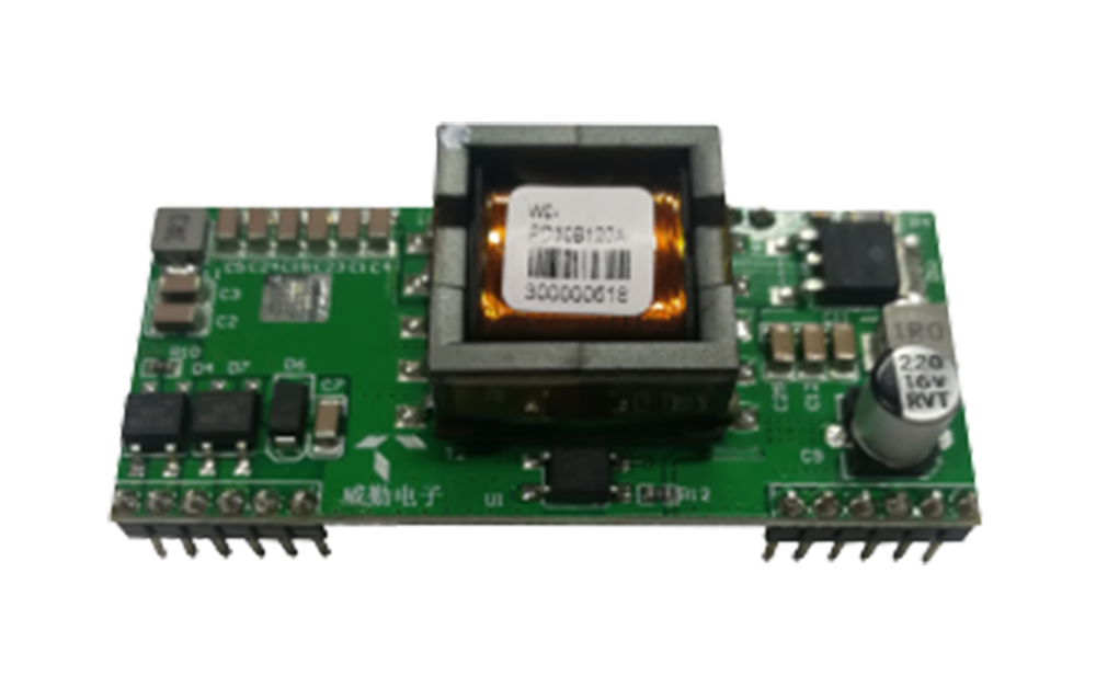
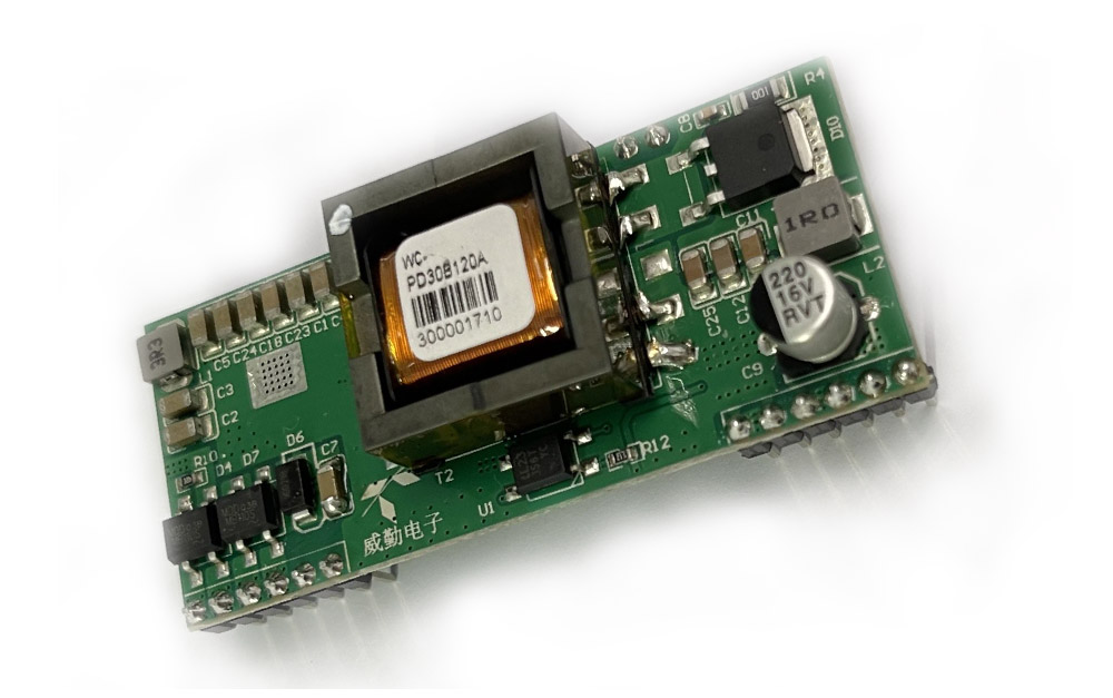
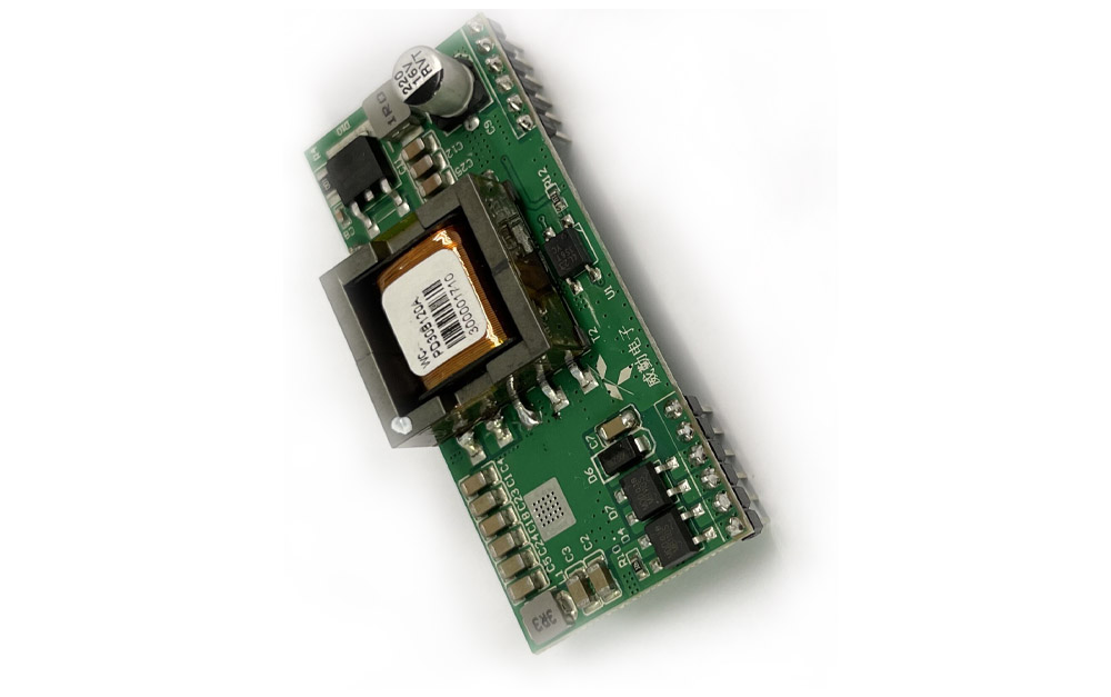
1.Product characteristics
- Compliance with IEEE802.3at standard.
- 38V~57V wide operating voltage range.
- Maximum output power up to 30W; Rated output: 12V/2.5A.
- The output ripple is less than 150 mV.
- Conversion efficiency can be as high as 87% (input: 48V output)12V@2.5A).
- Withovercurrent, short circuit, under voltage, surge andother excellent reliability and circuit protection.
- PCBA standard size: 62mm*27mm*14mm
- Input/Output: isolate 1500Vdc.
- High reliability: The design meets the 5 million hour average failure interval.
2.Scope of application
- Video and VoIP Phone
- RFID Reader
- Multiband Access Point
- Surveillance camera
3.Describe
The module is designed to extract power from conventional Class 5 Ethernet cable twisted pairs and meets the IEEE 802.3at Power-Ethernet (PoE) standard.At the same time, the module allows the power supply category to select "Intermediate Overlap" and "End Overlap" power supply without distinguishing polarity.
Based on the IEEE 802.3at standard, this paper establishes information connection about the connection status, device type, power consumption level of the receiving device PD, and then applies 30W power supply to port compatible devices based on PSE to power the PD through ethernet.
This module DC/DC converter works in a wide input voltage range and low ripple low noise output.The DC/DC converter also has built-in output overload, output short circuit and overtemperature protection, and provides a 1500Vdc (input/output) electrical isolation.
4. Mechanical dimensions

5.Pin definition
| Pin | Name | describe | |
| 1 | VA1 | This input pin is connected to the VA 2 and the central tap connected to the transformer, pins 1 and 2 of the RJ45 connector (RX).(There are two sets of bridge stacks added to the POE input to accommodate different PSE power supply directions) | |
| 2 | VA2 | This input pin is used with VA1 and central taps connected to transformers, pins 3 and 6 connected to RJ45 connectors (TX).(There are two sets of bridge stacks added to the POE input to accommodate different PSE power supply directions) | |
| 3 | VB1 | This input pin works with VB2 and connects to pins 4 and 5 of the RJ45 connector (POE input plus two sets of bridge stacks to accommodate different PSE end power supply directions) | |
| 4 | VB2 | This input pin works with VB1 and connects to pins 7 and 8 of the RJ45 connector (POE input plus two sets of bridge stacks to accommodate different PSE end power supply directions) | |
| 7 | GND | Negative DC output.This pin provides negative adjustment output | |
| 8 | GND | Negative DC output.This pin provides negative adjustment output | |
| 9 | Vout | The DC output of the positive pole.This pin provides positive adjustment output | |
| 10 | Vout | The DC output of the positive pole.This pin provides positive adjustment output | |
| 5,6,11,12 | NC | Hanging | |
6. Electrical characteristics
6.1 Absolute maximum rating parameter
| No | Parameter | Symbol | MIN | MAX | Units |
| 1 | DC Voltage | VCC | 38 | 57 | V |
| 2 | DC Voltage Surge 1ms | VSURGE | -0.6 | 80 | V |
| 3 | Ambient temperature | TS | -40 | 80 | ℃ |
*Exceeding the above rating may cause permanent damage to the product.Functional operations under these conditions are not recommended.
6.2 Recommended working conditions
| No | Parameter | Symbol | MIN | TYP | MAX | Units |
| 1 | Input voltage | VIN | 38 | 48 | 57 | V |
| 2 | Low Voltage Lock | VLOCK | 35 | — | — | V |
| 3 | Working temperature | TOP | -40 | 25 | 80 | ℃ |
*Applicable only to PS30B-120A maximum operating temperature.
6.3 DC Characteristic
| No | Parameter | Symbol | MIN | TYP | MAX | Units | Test Opinions |
| 1 | Standard Output Voltage | VDC | 11.5 | 12.0 | 12.2 | V | VIN=48V |
| 2 | Output Current(VIN=48V) | PWR | — | 2.5 | 2.8 | A | Wide voltage input 38-57V |
| 3 | Power adjustment rate | VLINE | — | 0.1 | — | % | @50% Load |
| 4 | Load Adjustment Rate | VLOAD | — | 1 | — | % | @VIN=48V |
| 5 | Ripple Output Noise | VRN | — | 150 | 200 | mVp-p | @Maximum Load |
| 6 | Minimum Load | RLOAD | 10 | — | — | mA | |
| 7 | Short circuit duration | TSC | — | — | ∞ | sec | |
| 8 | Efficiency (load 80%) | EFF | 85 | 88 | — | % | |
| 9 | Isolation Voltage (I/O) | VISO | — | — | 1500 | VPK | |
| 10 | Temperature coefficient | Tc | — | 0.02 | — | % | Per ℃ |
| 11 | Efficiency | Tr | — | 150 | 250 | ms | VIN=48V VOUT=max |
1: Typical number is 25 C, nominal voltage is 48V, for auxiliary design only.
2: Output ripple and noise can be reduced by an external filter, see the application instructions.
3: If operated under the specified minimum load, the module emits audible noise and may cause PSE malfunction.
7 Functional Description
7.1 input
WC-PD30B120A input end with bridge stack ensures input polarity protection, user can choose the connection mode as needed.

7.2 PD Signature
When the module is connected to the cable, it will automatically provide the Power Device (PD) signature to the PSE when needed.The PSE recognizes that the PD is connected to that line and provides power

7.3 Power Classification
WC-PD30B120A uses IEEE802.3at standard and runs with Class 4 (30W) power rating by default.
| Define criteria | Cable requirements | Grading parameters | Power Supply Characteristics |
| IEEE802.3at(PoE Plus) | CAT5 cable or CAT6 cable | Maximum power required for Class4 devices is 13W~25.5W |
The DC voltage ranges from 42 to 57V, with a typical value of 48V. Typical operating current is 10~600mA; typical output power: 30W; Class4 rating supported by electrical equipment |
| IEEE802.3af(PoE) | CAT5 cable | Maximum power required for Class0 devices is 0~12.95W | The DC voltage ranges from 38 to 57V, with a typical value of 48V. Typical operating current is 10~350mA; typical output power: 15.4W; The overload detection current is 350~500mA. Provide 4 Class Power Requests for PD Devices ranging from 3.84 to 12.95W |
| The maximum power required for Class1 devices is 0~3.84W | |||
| The maximum power required for Class2 devices is 3.85W~6.49W | |||
| The maximum power required for Class3 devices is 6.5W~12.95W |
8. PoE Product naming rules

9. Typical applications
This module is used in PSE network cable to convert electric energy to DC-DC to the required voltage of equipment without affecting data signal transmission. It conforms to ieee802.3at standard and is used by all equipment terminals

10. Test waveform diagram
Typical features:Vout=12
 |
 |
| Efficiency (Vout = 12 V) | Output voltage (input 48V) |
 |
 |
| Maximum temperature of components Conditions (ambient temperature: 27 ℃; Output power: 12V / 2.5A; frequency: 3H) |
Input voltage & output voltage |
 Noise (VIN = 42V, IO = 2.5A, 5 ~ 20MHz bandwidth) |
 Output response & load (12V / 0.02A) |
 Noise (VIN = 48V, IO = 2.5A, 5 ~ 20MHz bandwidth) |
 Output response & load (12V / 1A) |
 Noise (VIN = 57V, IO = 2.5A, 5 ~ 20MHz bandwidth) |
 Output response & load (12V / 2.5A) |


